USB OTG product must pass the following tests:
•Physical inspection for:
◦micro-AB receptacle
◦user interface display
•Signal Quality as a host (A-Device)
•Signal Quality as a device (B-Device)
•OTG Electrical Test (OET)
•OTG Protocol Test (OPT)
•Interoperability with devices listed on the targeted peripheral list
•Submission of completed USB OTG Compliance Checklist
2010年11月9日 星期二

2010年10月14日 星期四
展頻時脈產生器
展頻時脈的技術是頻率調變( FM )的一種應用,相反地,頻率調變通常會伴隨產生展頻的效果。展頻時脈最基本的想法,是稍微地調變時脈訊號的頻率,造成時脈訊號的能量,分散到一個可以控制的小範圍內。在經過展頻調變之後,頻譜上每一個諧波的峰值能量將會消失,如圖一所示:在越高次諧波項,其所產生的展頻量會越大,因此,其峰值能量的衰減會越明顯。會受到EMI限制的是在特定頻率的峰值發射量( peak emission ),而不是在整個頻譜的平均峰值發射量,因此,利用展頻時脈可以提供一個比較低的 EMI 訊號。
根據調變訊號的頻率範圍,展頻的模式主要可以區分為三種:中心展頻( center-spread ),向下展頻( down-spread ),及向上展頻( up-spread )。中心展頻的調變,如圖二 ( a ) 所示:其調變頻率是以 fnom 為中心,然後在 ( 1+ d/2 ) fnom 和 ( 1- d/2 ) fnom 之間變化。其中, d 是指相對於 fnom 的展頻百分比,而 fm 是指調變的頻率。這種調變模式提供了一個跟非展頻模式時相同的平均頻率。例如:一個 2.4GHz 的時脈有 1%的中心展頻調變,這代表其頻率範圍會在 2.388GHz 和 2.412GHz 之間做變化。
這個技術已經被應用在SATA之類的高速訊號
來源出處:http://memo.cgu.edu.tw/Secretariat/news/74/research/research_1.htm
根據調變訊號的頻率範圍,展頻的模式主要可以區分為三種:中心展頻( center-spread ),向下展頻( down-spread ),及向上展頻( up-spread )。中心展頻的調變,如圖二 ( a ) 所示:其調變頻率是以 fnom 為中心,然後在 ( 1+ d/2 ) fnom 和 ( 1- d/2 ) fnom 之間變化。其中, d 是指相對於 fnom 的展頻百分比,而 fm 是指調變的頻率。這種調變模式提供了一個跟非展頻模式時相同的平均頻率。例如:一個 2.4GHz 的時脈有 1%的中心展頻調變,這代表其頻率範圍會在 2.388GHz 和 2.412GHz 之間做變化。
這個技術已經被應用在SATA之類的高速訊號
來源出處:http://memo.cgu.edu.tw/Secretariat/news/74/research/research_1.htm
2010年10月12日 星期二
香港電子展
由於最近要電子展, 許多的客戶都想要拿我們家的Solution 去展覽, 只能說Very Very Busy. 我就要準備5種東西給老闆及客人. 但好死不死. Nelson 和STB 及Pocket 都有問題. 功虧一簣.
後來想想自己在工作快5年的印象中. 我弄的Demo unit好像掛掉的機率超高. 每一個Sample 都花了很長時間在弄. 但最後驗證檢查的部份似乎做的不是很好. 還好sample 的可靠度也是. 以前是系統廠的RD 就還好, 現在是Design house的AE. sample 就很重要了.
之後真的是要改進這個問題, 不然就混不下去了
昨天和凱哥和Rhino吃飯的時候, 談到某部門A咖 到這個部門變成C咖, 聽了之後我有一些感觸
後來想想自己在工作快5年的印象中. 我弄的Demo unit好像掛掉的機率超高. 每一個Sample 都花了很長時間在弄. 但最後驗證檢查的部份似乎做的不是很好. 還好sample 的可靠度也是. 以前是系統廠的RD 就還好, 現在是Design house的AE. sample 就很重要了.
之後真的是要改進這個問題, 不然就混不下去了
昨天和凱哥和Rhino吃飯的時候, 談到某部門A咖 到這個部門變成C咖, 聽了之後我有一些感觸
2010年8月23日 星期一
2010年8月3日 星期二
RF 名詞
反射電壓波振幅與入射電壓波振幅的比值,稱為反射係數Γ(reflection coefficient)
=>
匹配負載(Γ = 0)的反射損失為無限大dB(沒有反射的功率);反之,造成全反射( Γ
= 1)的負載,其反射損失為0dB(所有的入射功率均被反射回去)。
若負載與傳輸線匹配,反射係數為零,線上電壓波的振幅大小V(z)= Vo+ 為定值,不會隨z位置不同而改變。如果負載不匹配,反射波加上入射波,在傳輸線上形成駐波(standing wave),線上的電壓波振幅大小就不再是定值,此時電壓波會有週期性的高低起伏,最高的電壓為Vmax,最低電壓為Vmin。所以,另有一個指標也可用以描述負載匹配的程度,稱為駐波比(standing wave ratio, SWR)
SWR為一實數,並且 1≦SWR≦∞,當SWR = 1(0dB)時,表示負載完全匹配。
史密斯圖只是電壓反射係數 Γ 的極座標圖。令反射係數Γ = Γ ejθ,其大小
Γ,就是Γ 點到圓心的距離(Γ≦1),相位角θ(-180o≦ θ ≦180o)則是以圓心右側的橫軸為零度,逆時針計算到Γ 點的角度。任何 Γ≦1的反射係數,均可在史密斯圖上找到唯一對應的一點。以|Γ|定值所畫的圓,成為定|Γ|圓(constant-Γ circle)
=>
匹配負載(Γ = 0)的反射損失為無限大dB(沒有反射的功率);反之,造成全反射( Γ
= 1)的負載,其反射損失為0dB(所有的入射功率均被反射回去)。
若負載與傳輸線匹配,反射係數為零,線上電壓波的振幅大小V(z)= Vo+ 為定值,不會隨z位置不同而改變。如果負載不匹配,反射波加上入射波,在傳輸線上形成駐波(standing wave),線上的電壓波振幅大小就不再是定值,此時電壓波會有週期性的高低起伏,最高的電壓為Vmax,最低電壓為Vmin。所以,另有一個指標也可用以描述負載匹配的程度,稱為駐波比(standing wave ratio, SWR)
SWR為一實數,並且 1≦SWR≦∞,當SWR = 1(0dB)時,表示負載完全匹配。
史密斯圖只是電壓反射係數 Γ 的極座標圖。令反射係數Γ = Γ ejθ,其大小
Γ,就是Γ 點到圓心的距離(Γ≦1),相位角θ(-180o≦ θ ≦180o)則是以圓心右側的橫軸為零度,逆時針計算到Γ 點的角度。任何 Γ≦1的反射係數,均可在史密斯圖上找到唯一對應的一點。以|Γ|定值所畫的圓,成為定|Γ|圓(constant-Γ circle)
2010年7月28日 星期三
AUDIO CROSSOVER
What is a crossover? People can hear sound frequencies from 20-20000Hz. There is no one speaker capable of producing all frequencies throughout this range. Therefore, multiple speakers must be used. Usually, it is damaging for a speaker to produce frequencies lower than what it was designed for. Also, if two speakers produce sound at the same frequencies, then the sound at those frequencies will be louder. For these reasons, some type of circuit is necessary to make sure that each speaker only produces a certain set of frequencies. That circuit is a crossover
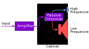
Audio crossovers are a class of electronic filters designed specifically for use in audio applications, especially hi-fi. Individual loudspeaker drivers are incapable of covering the entire audio spectrum, from low frequencies to high frequencies, with acceptable volume and lack of distortion by themselves.
Therefore a combination of multiple loudspeakers or drivers, each catering to a different frequency band, is the design pattern for most hi-fi speaker systems. Crossovers serve the purpose of splitting the audio signal into separate frequency bands which can be handled by individual loudspeaker drivers optimized for those bands. An audio crossover may also be constructed mechanically and is commonly found in full-range speakers, portions of whose cones/dust caps/whizzer cones are decoupled at progressively higher frequencies.

Reference:
1.http://www.lenardaudio.com/education/06_x-over.html
2.http://en.wikipedia.org/wiki/Audio_crossover
3.http://en.wikipedia.org/wiki/Linkwitz-Riley_filter
Audio crossovers are a class of electronic filters designed specifically for use in audio applications, especially hi-fi. Individual loudspeaker drivers are incapable of covering the entire audio spectrum, from low frequencies to high frequencies, with acceptable volume and lack of distortion by themselves.
Therefore a combination of multiple loudspeakers or drivers, each catering to a different frequency band, is the design pattern for most hi-fi speaker systems. Crossovers serve the purpose of splitting the audio signal into separate frequency bands which can be handled by individual loudspeaker drivers optimized for those bands. An audio crossover may also be constructed mechanically and is commonly found in full-range speakers, portions of whose cones/dust caps/whizzer cones are decoupled at progressively higher frequencies.
Reference:
1.http://www.lenardaudio.com/education/06_x-over.html
2.http://en.wikipedia.org/wiki/Audio_crossover
3.http://en.wikipedia.org/wiki/Linkwitz-Riley_filter
2010年7月21日 星期三
LC RF filter circuits: Low-pass filters
LC RF filter circuits: Low-pass filters: "Low-pass LC filters are recognized by having the inductor (or inductors) in series with the signal path and the capacitors shunted across t..."
LC RF filter circuits: High-pass filters
LC RF filter circuits: High-pass filters: "A high-pass filter (HPF) attenuates signal frequencies below the -3-dB cutoff frequency and passes signal frequencies above the cutoff frequ..."
2010年7月13日 星期二
LINE OUT , HEADPHONE OUT
Line out
The signal out of line out remains at a constant level, regardless of the current setting of the volume control. You can connect recording equipment to line out and record the signal, without having to listen to it through the device's speaker, and without the loudness of the recording changing if you change the volume control setting of the device while you are recording.
The impedance is around 100 Ω, the voltage can reach 2 volts peak-to-peak with levels referenced to -10 dBV (300 mV) at 10 kΩ, and frequency response of most modern equipment is advertised as 20 Hz - 20 000 Hz (although other factors influence frequency response).[citation needed]
This impedance level is much higher than the usual 4 - 8 Ω of a speaker or 32 Ω of headphones, such that a speaker connected to line out essentially short circuits the op-amp. Even if the impedances would match, yielding the theoretical maximum power transfer of 50%, the power supplied through line out is not enough to drive a speaker.
Headphone amplifier
headphone amplifier is a small power amplifier that can be connected to a standard headphone jack or (usually) the line output of an audio source. The headphone amplifier improves the sound quality by increasing the amount of power available to move the transducer, increasing the control that the source has over just where the transducer is in space.
Many headphone amplifiers have an output impedance in the range of 20 - 50 Ohms. The 1996 IEC 61938 standard recommended an output impedance of 120 Ohms.
The signal out of line out remains at a constant level, regardless of the current setting of the volume control. You can connect recording equipment to line out and record the signal, without having to listen to it through the device's speaker, and without the loudness of the recording changing if you change the volume control setting of the device while you are recording.
The impedance is around 100 Ω, the voltage can reach 2 volts peak-to-peak with levels referenced to -10 dBV (300 mV) at 10 kΩ, and frequency response of most modern equipment is advertised as 20 Hz - 20 000 Hz (although other factors influence frequency response).[citation needed]
This impedance level is much higher than the usual 4 - 8 Ω of a speaker or 32 Ω of headphones, such that a speaker connected to line out essentially short circuits the op-amp. Even if the impedances would match, yielding the theoretical maximum power transfer of 50%, the power supplied through line out is not enough to drive a speaker.
Headphone amplifier
headphone amplifier is a small power amplifier that can be connected to a standard headphone jack or (usually) the line output of an audio source. The headphone amplifier improves the sound quality by increasing the amount of power available to move the transducer, increasing the control that the source has over just where the transducer is in space.
Many headphone amplifiers have an output impedance in the range of 20 - 50 Ohms. The 1996 IEC 61938 standard recommended an output impedance of 120 Ohms.
2010年7月7日 星期三
Adjacent Channel Selectivity
Adjacent Channel Selectivity
This characteristic deals with stations immediately adjacent i.e.(200KHz away) that might intrude on the station you have tuned. If the tuner is equipped with switchable IF bandwidth, this position would be known as 'wide'. It offers the widest bandwidth through which the signal must pass through to be decoded. A typical level is 8dB. (higher number value = better).
Alternate Channel Selectivity
This characteristic deals with stations adjacent (400KHz away) that might intrude on the station you have tuned. If the tuner is equipped with a switchable IF bandwidth, this position would be known as 'wide'. A typical level is about 50dB. (higher number value = better).
This characteristic deals with stations immediately adjacent i.e.(200KHz away) that might intrude on the station you have tuned. If the tuner is equipped with switchable IF bandwidth, this position would be known as 'wide'. It offers the widest bandwidth through which the signal must pass through to be decoded. A typical level is 8dB. (higher number value = better).
Alternate Channel Selectivity
This characteristic deals with stations adjacent (400KHz away) that might intrude on the station you have tuned. If the tuner is equipped with a switchable IF bandwidth, this position would be known as 'wide'. A typical level is about 50dB. (higher number value = better).
2010年7月1日 星期四
2010年6月28日 星期一
TDMA Noise
TDMA (time-division multiple-access) time-slot sharing technique that results in high-power RF in the 800MHz to 900MHz or 1800MHz to 1900MHz bands.
The transmitter current, which can exceed 1A, pulses during a phone call at a repetition rate of 217Hz and pulse width of about 0.5ms.
If current pulses couple to the audio circuitry, the harmonic-rich 217Hz signal results in the audible buzz.
The transmitter current, which can exceed 1A, pulses during a phone call at a repetition rate of 217Hz and pulse width of about 0.5ms.
If current pulses couple to the audio circuitry, the harmonic-rich 217Hz signal results in the audible buzz.
2010年6月26日 星期六
支持CMMB、DAB、T-DMB/DVB-T/DVB-H多款标准的移动数字电视接收芯片
摩威科技近日对外宣布,支持中国移动多媒体广播标准CMMB,数字音频广播标准DAB,以及国际移动电视标准T-DMB,DVB-T/DVB-H的MV2001G移动数字电视接收芯片将于近期投放市场。


看來也是SOC chip 而且重點又多了T-DMB,DVB-T/DVB-H 等數位電視的功能
應該是強勁的對手, 待後續觀察
摩威科技
http://www.mavrixtech.com/index.htm
摩威科技
http://www.mavrixtech.com/index.htm
十大行動裝置驅動處理器市場爆炸性成長
市場研究機構Jon Peddie Research認為,電子書閱讀器(eBooks)、平板電腦(tablets)、智慧型手機(smartphones)等消費性行動裝置市場正經歷爆炸性成長,也創造了對多媒體處理器、應用處理器不斷成長的需求。
Frontier Silicon reaches 10 million milestone
Frontier solution 達成了10 million 的成績
原文 http://www.frontier-silicon.com/media/releases/10/0210_10mAus.htm
Sales to double in the next three years driven by new market growth
原文 http://www.frontier-silicon.com/media/releases/10/0210_10mAus.htm
Sales to double in the next three years driven by new market growth
2008年6月21日 星期六
44b0x Embeded System lab 1-1 LED Control
昨天稍為簡介了控制I/O所需的register,今天就把程式post上來,我想程式很簡單,有寫過DSP或是8051的人應該都會寫。
#include "44b0x.h" //定義相關register的位置
#include "DataType.h"U32 pIrqStart, pIrqFinish, pIrqHandler;void ledalloff(); //LED全滅void ledallon(); //LED全暗void ledon(int i); //單一個LED 亮void ledshift(int i);
//3個LED做跑馬燈
/*********************************************************/
int main(void)
{
ledalloff();
ledallon();
ledshift(1);
return 0;
}
void ledalloff(){rPCONC=0x0f05ff54; rPDATC=0xfff1;}
void ledallon(){rPCONC=0x0f05ff54;rPDATC=0xfffe;}
void ledon(int i)
{int offset;offset=1;offset=offset< rPDATC=0xfff0offset;}
void ledshift(int i)
{int j=3;while(i--) {while(j--){ledon(i);}}}
#include "44b0x.h" //定義相關register的位置
#include "DataType.h"U32 pIrqStart, pIrqFinish, pIrqHandler;void ledalloff(); //LED全滅void ledallon(); //LED全暗void ledon(int i); //單一個LED 亮void ledshift(int i);
//3個LED做跑馬燈
/*********************************************************/
int main(void)
{
ledalloff();
ledallon();
ledshift(1);
return 0;
}
void ledalloff(){rPCONC=0x0f05ff54; rPDATC=0xfff1;}
void ledallon(){rPCONC=0x0f05ff54;rPDATC=0xfffe;}
void ledon(int i)
{int offset;offset=1;offset=offset< rPDATC=0xfff0offset;}
void ledshift(int i)
{int j=3;while(i--) {while(j--){ledon(i);}}}
44B0xEmbeded System lab 1-1
S3C44B0X主要的功能有:
·2.5V Static ARM7TDMI CPU core with 8KB cache . (SAMBA II bus architecture up to 66MHz)
· External memory controller. (FP/EDO/SDRAM Control, Chip Select logic)
· LCD controller (up to 256 color DSTN) with 1-ch LCD-dedicated DMA.
· 2-ch general DMAs / 2-ch peripheral DMAs with external request pins
· 2-ch UART with handshake(IrDA1.0, 16-byte FIFO) / 1-ch SIO· 1-ch multi-master IIC-BUS controller
· 1-ch IIS-BUS controller
· 5-ch PWM timers & 1-ch internal timer
· Watch Dog Timer
· 71 general purpose I/O ports / 8-ch external interrupt source
· Power control: Normal, Slow, Idle, and Stop mode
· 8-ch 10-bit ADC.· RTC with calendar function.· On-chip clock generator with PLL.
S3C44B0X 共有 71 多功能的I/O Port,主要可以分成7個Group:
— Two 9-bit input/output ports. (Port E and F)
— Two 8-bit input/output ports. (Port D and G)
— One 16-bit input/output port. (Port C)— One 10-bit output port. (Port A)
— One 11-bit output port. (Port B)EVM板上有3個LED在PortC中的第115到117隻腳,也就是115 pin DATA19/IISCLK/GPC3116 pin DATA18/IISDI/GPC2117 pin DATA17/IISDO/GPC1
首先想要控制Led就必須先了解3個Register
PCONC 0x01D20010: port control register.決定多功能pin I/O的功能。
00:input 01:output.
PDATC 0x01D20014: port data register.
如果是輸出port,register中的資料就是輸出的資料,如果是輸入port就是資料讀取的register。PUPC 0X01D20018: pull-up resistor. 0:pull-up resistor enable.待續...
·2.5V Static ARM7TDMI CPU core with 8KB cache . (SAMBA II bus architecture up to 66MHz)
· External memory controller. (FP/EDO/SDRAM Control, Chip Select logic)
· LCD controller (up to 256 color DSTN) with 1-ch LCD-dedicated DMA.
· 2-ch general DMAs / 2-ch peripheral DMAs with external request pins
· 2-ch UART with handshake(IrDA1.0, 16-byte FIFO) / 1-ch SIO· 1-ch multi-master IIC-BUS controller
· 1-ch IIS-BUS controller
· 5-ch PWM timers & 1-ch internal timer
· Watch Dog Timer
· 71 general purpose I/O ports / 8-ch external interrupt source
· Power control: Normal, Slow, Idle, and Stop mode
· 8-ch 10-bit ADC.· RTC with calendar function.· On-chip clock generator with PLL.
S3C44B0X 共有 71 多功能的I/O Port,主要可以分成7個Group:
— Two 9-bit input/output ports. (Port E and F)
— Two 8-bit input/output ports. (Port D and G)
— One 16-bit input/output port. (Port C)— One 10-bit output port. (Port A)
— One 11-bit output port. (Port B)EVM板上有3個LED在PortC中的第115到117隻腳,也就是115 pin DATA19/IISCLK/GPC3116 pin DATA18/IISDI/GPC2117 pin DATA17/IISDO/GPC1
首先想要控制Led就必須先了解3個Register
PCONC 0x01D20010: port control register.決定多功能pin I/O的功能。
00:input 01:output.
PDATC 0x01D20014: port data register.
如果是輸出port,register中的資料就是輸出的資料,如果是輸入port就是資料讀取的register。PUPC 0X01D20018: pull-up resistor. 0:pull-up resistor enable.待續...
44B0X EVM板介紹
之前Post 在樂多Blog,日子一久了發現忘了帳號密碼@@",所以還是移植到Google的Blog
今天就介紹一下44B0X EVM 板,首先它是Samsung S3C44B0X的ARM CPU,是ARM 7TDMI,是目前ARM最低階的CPU。T:表示它有支援Thumb指令。D:??忘記了。M:支援硬體的Multiplex。I:???忘記了。@@""其它的還有J:支援硬體的JVM、E:有DSP含在其中。現在TI也有出OMAP系統的Chip,裡面含有ARM9 及C54x的DSP,很合適做多媒體的應用。
主要板子上有這些設備:
1. Samsung S3C44B0X ARM7 32-bit CPU (66MHz)
2. 2MB Flash
3. 8MB SDRAM
4. RS-232C port x 2
5. RJ-45 10 Base-T Ethernet interface
6. USB 1.1 device 介面
7. IDE 介面
8. LCD 介面
9. 4個 Key 及 1 個 Reset 鍵
10. 3個 Led
11. 蜂鳴器 (要自行加)
12. 音頻介面
13. RTC 預留鋰電池底座 (要再自行加底座)
14. I2C EEPROM 24C02
15. JTAG connector 14 Pin
16. 40 Pin信號插槽 x4
今天就介紹一下44B0X EVM 板,首先它是Samsung S3C44B0X的ARM CPU,是ARM 7TDMI,是目前ARM最低階的CPU。T:表示它有支援Thumb指令。D:??忘記了。M:支援硬體的Multiplex。I:???忘記了。@@""其它的還有J:支援硬體的JVM、E:有DSP含在其中。現在TI也有出OMAP系統的Chip,裡面含有ARM9 及C54x的DSP,很合適做多媒體的應用。
主要板子上有這些設備:
1. Samsung S3C44B0X ARM7 32-bit CPU (66MHz)
2. 2MB Flash
3. 8MB SDRAM
4. RS-232C port x 2
5. RJ-45 10 Base-T Ethernet interface
6. USB 1.1 device 介面
7. IDE 介面
8. LCD 介面
9. 4個 Key 及 1 個 Reset 鍵
10. 3個 Led
11. 蜂鳴器 (要自行加)
12. 音頻介面
13. RTC 預留鋰電池底座 (要再自行加底座)
14. I2C EEPROM 24C02
15. JTAG connector 14 Pin
16. 40 Pin信號插槽 x4
訂閱:
文章 (Atom)